
PT.SARTINDO LAMTABO SEJAHTERA
Visit us
JL.RAYA GATOT SUBROTO NO. 89 KM 6.2 JATIUWUNG TANGERANG
Phone WA (+62)21 590284 Handphone 087883986257
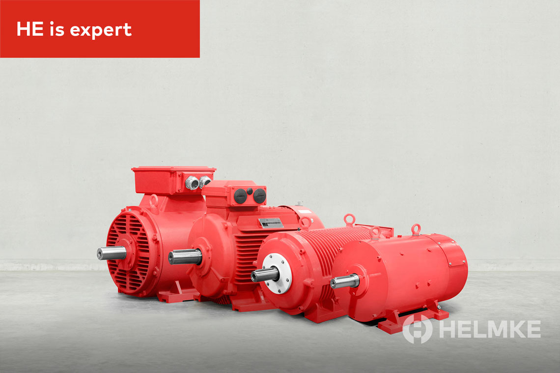
HELMKE PLUS SQUIRREL CAGE IEC STANDARD MOTOR
DISTRIBUTOR HELMKE plus
IEC Low-voltage Motors
with Squirrel Cage Rotor
for Catalogue
New catalogue squirrel-cage standard motor series
HELMKE plus
IEC Low-voltage Motors
with Squirrel Cage Rotor
Table of Contents
1 General specification 3
1.1 Standards and regulation .................................................................................................................................................... 3
1.2 Conditions of installation ..................................................................................................................................................... 3
1.3 Painting .................................................................................................................................................................................... 4
1.4 Insulation and temperature rise ......................................................................................................................................... 4
1.5 Tolerances ............................................................................................................................................................................... 5
1.6 Mechanical design ................................................................................................................................................................. 6
1.7 Mounting arrangements ...................................................................................................................................................... 6
1.8 Terminal boxes ....................................................................................................................................................................... 7
1.9 Belt drive .................................................................................................................................................................................. 8
1.10 Vibration behaviour ............................................................................................................................................................... 8
1.11 Maximum operating speed .................................................................................................................................................. 8
1.12 Lubrication and maintenance of bearings ....................................................................................................................... 8
1.13 Electrical design ..................................................................................................................................................................... 9
1.14 Motor protection ................................................................................................................................................................... 11
1.15 Three-phase squirrel-cage motors driven by frequency inverters ............................................................................. 12
2 Aluminium Motor 14
2.1 Overview aluminium motors .............................................................................................................................................. 14
2.2 Terminal box .......................................................................................................................................................................... 15
2.3 Materials ................................................................................................................................................................................. 15
2.4 Bearings .................................................................................................................................................................................. 15
2.5 Anti-condensation heating ................................................................................................................................................. 17
2.6 Noise characteristics ............................................................................................................................................................ 17
2.7 Position and dimensions of the key .................................................................................................................................. 17
2.8 Technical data IE2 ................................................................................................................................................................ 18
2.9 Dimensions IE2 ..................................................................................................................................................................... 22
2.10 Technical data IE3 ............................................................................................................................................................... 24
2.11 Dimensions IE3 ..................................................................................................................................................................... 27
3 Cast Iron Motors 29
3.1 Overview cast iron motors ................................................................................................................................................. 29
3.2 Terminal box ........................................................................................................................................................................ 30
3.3 Materials ............................................................................................................................................................................... 30
3.4 Bearings .................................................................................................................................................................................. 31
3.5 Anti-condensation heating ................................................................................................................................................ 34
3.6 Noise characteristics ........................................................................................................................................................... 34
3.7 Position and dimensions of the key ................................................................................................................................. 35
3.8 Technical data IE2 ................................................................................................................................................................ 36
3.9 Dimensions frame size 63...180 IE2 .................................................................................................................................. 44
3.10 Dimensions frame size 200...355 IE2 ............................................................................................................................... 47
3.11 Technical data IE2 ............................................................................................................................................................... 50
3.12 Dimensions frame size 63...180 IE3 .................................................................................................................................. 56
3.13 Dimensions frame size 200...355 IE3 ............................................................................................................................... 59
Revisions
All technical data, outputs, dimensions and weights, stated in this catalogue, are subject to change without
notice. Illustrations do not purport to show constructional details.
General specification 3
1 General specification
1.1 Standards and regulation
The motors comply with the relevant standards and regulations, especially:
Electrical
IEC-Standard EN-Standard Content
IEC 60034-1 EN 60034-1 Rotating electrical machines – Part 1: Rating and performance
IEC 60034-8 EN 60034-8 Rotating electrical machines – Part 8: Terminal markings and direction
of rotation
IEC 60034-12 EN 60034-12 Rotating electrical machines – Part 12: Starting performance of singlespeed
three-phase cage induction motors
IEC 60034-30-1 EN 60034-30-1 Rotating electrical machines – Part 30-1: Efficiency classes of line
operated AC motors (IE code)
IEC 60038 EN 60038 CENELEC standard voltages
Mechanical
IEC-Standard EN-Standard Content
IEC 60072 EN 50347 Dimensions and outputs
IEC 60034-5 EN 60034-5 Rotating electrical machines – Part 5: Degrees of protection provided by
integral design of rotating electrical machines (IP code) – Classification
IEC 60034-6 EN 60034-6 Rotating electrical machines – Part 6: Methods of cooling (IC-Code)
IEC 60034-7 EN 60034-7 Rotating electrical machines – Part 7: Classification of types of
construction, mounting arrangements and terminal box position (IMcode)
IEC 60034-9 EN 60034-9 Rotating electrical machines – Part 9: Noise limits
IEC 60034-14 EN 60034-14 Rotating electrical machines – Part 14: Mechanical vibration of certain
machines with shaft heights 56 mm and higher – Measurement,
evaluation and limits of vibration severity
1.2 Conditions of installation
The motors are designed for operation at altitudes ≤1000 m above sea-level and at coolant temperature of up to
40 °C. Exceptions are indicated on the rating plate.
The motors comply with protection degree IP55 according EN / IEC 60034-5 (higher protection degrees on
request).
Motors with standard design for horizontal mounting arrangements are suitable for indoor and protected
outdoor installation, climate group MODERATE (temperature of coolant −20 °C to +40 °C).
In case of unprotected outdoor installation or aggravating climatic conditions (moisture category wet, climate
group WORLDWIDE, extremely dusty site conditions, aggressive industrial atmosphere, danger of storm rain and
coastal climate, danger of attack by termites, etc.), as well as vertical mounting, special measures are required,
such as:
§ ØProtective cowl (for vertical mounting with shaft-down)
§ ØFor vertical mounting with shaft-up flange drainage and additional bearing seal, if necessary
§ ØSpecial painting
§ ØTreatment of winding with moisture protection varnish
§ ØAnti-condensation heating (anti-condensation heating of winding, if necessary)
§ ØCondensation drain holes
4 General specification
The special measures to be applied have to be agreed with us once the conditions of installation have been
clarified.
F The respective conditions of installation have to be clearly indicated in the order.
1.3 Painting
Standard painting
Suitable for climate group Moderate according to EN / IEC 60721-2-1, i. e. indoor and outdoor installation:
§ Øshort-term: up to 100 % humidity at temperatures up to +30 °C,
§ Ølong-term: up to 85 % humidity at temperatures up to +25 °C
Special painting K1
Suitable for climate group Worldwide according to EN / IEC 60721-2-1, , i. e. outdoor installation in aggressive
chemical atmosphere and coastal climate:
§ short-term: up to 100 % humidity at temperatures up to +35 °C
§ long-term: up to 98 % humidity at temperatures up to +30 °C
Special designs (on request)
§ Special painting K2 (additional treatment of internal motor parts)
§ Special painting in case of alkalis
§ Special painting according to customers’ requirements
1.4 Insulation and temperature rise
The insulation of the motors complies with temperature class F according EN 60034-1
The table shown on the side specifies the heating (ΔT*) and maximum
temperatures the hottest points of the coil (Tmax) according to the heat classes
of the standard EN / IEC 60034–1.
Class ΔT Tmax
B 80 K 130° C
F 105 K 155° C
H 125 K 180° C
F In case of coolant temperature of 40 °C motors in standard design are only utilized according
temperature class B – with an overtemperature limit of 80 K. This also applies for the rated
voltage range according EN / IEC 60038. Exceptions are shown on the selection tables.
Derating at coolant temperatures over 40 °C
Temperature of coolant 45 °C 50 °C 55 °C 60 °C
Reduction of nominal power to approx. 95 % 90 % 85 % 80 %
When a winding is utilized according to temperature class F (105 K), no derating is required up to a coolant
temperature of 60 °C.
F This does not apply to motors which are already utilized according to thermal class F in their
standard design.
General specification 5
Installation at altitudes of more than 1000 m above sea level (also see EN / IEC 60034-1)
In case of higher altitudes and coolant temperature of 40°C the
nominal power has to be reduced approximately to the values
defined in the table beside.
Temperature
class
Altitude
2000 m 3000 m 4000 m
B 92 % 84 % 76 %
F 89 % 79 % 68 %
Installation at altitudes of more than 1000 m above sea level (also see EN / IEC 60034-1)
If the full nominal power according to the selection table is
necessary, the temperature of the coolant is to be decreased
according to the table beside.
Temperature
class
Altitude
2000 m 3000 m 4000 m
B 32 °C 24 °C 16 °C
F 30 °C 19 °C 9 °C
1.5 Tolerances
In consideration of the manufacturing tolerances and material deviations in the used raw materials, the
tolerances for industrial motors according to EN / IEC 60034-1 are permitted for the assured values. The
following notes in this regard are included in the standard:
§ An assurance of all or any of the values according to the table is not mandatorily required. Assured values to
which permissible deviations are to apply must be expressly stated in the offers. The permissible deviations
have to match the table.
§ If there is a permissible deviation only in one direction, the value in the other direction is not limited.
Values for Tolerannce
Efficiency class(η)
(for indirect assessment)
−0.15 · (1 − η) for PN ≤ 50 kW
−0.10 · (1 − η) for PN > 50 kW
Power factor (cos ϕ) −⅙ · (1 – cos ϕ), at least 0.02, at most 0.07
Slippage (s) (for rated load in condition at
operating temperature)
±20 % of the assured slippage for PN ≥ 1 kW
±30 % of the assured slippage for PN < 1 kW
Locked rotor current (IA)
(in the intended start switching)
+20 % of the assured locked rotor current
without bottom limitation
Locked rotor torque (TA) −15 % and +25 % of the assured locked rotor torque
(+25 % may be exceeded upon agreement)
Pull-up torque (TS) −15 % of the assured value
Tilting moment (TB) −10 % of the assured value
(after application of this tolerance, TB/TN is at least 1.6)
Inertia moment (J) ±10 % of the assured value
Mechanische Toleranzen
According to IEC 60072-1 / EN 50347 the
tolerances on mechanical dimensions of
electric motors given beside are permitted.
Note: The holes at the shaft end correspond
with DIN 332
Parameter Code Area Tolerance
Frame size H up to 250
> 250
0.5 mm
1 mm
Diameter of shaft
end
D-DA from 11 to 28 mm
from 38 to 48 mm
from 55 to 100 mm
j6
k6
m6
Hub key width F-FA h9
Flange centring N up to 132
> 132
j6
h6
6 General specification
1.6 Mechanical design
Protection degrees
Protection degrees for electrical machines are designated in accordance with EN / IEC 60034-5 by the letters IP
and two characteristic numerals.
First numeral:
Protection against contact and ingress of foreign
bodies
Second numeral:
Protection against ingress of water
IP Description
0 No special protection
1 Protection against solid foreign bodies larger
than 50 mm (Example: inadvertent contact
with the hand)
2 Protection against solid foreign bodies larger
than 12 mm (Example: inadvertent contact
with the fingers)
3 Protection against solid foreign bodies larger
than 2.5 mm (Example: Wires, tools)
4 Protection against solid foreign bodies larger
than 1 mm (Example: Wires, bands)
5 Protection against dust (harmful deposits of
dust)
6 Total protection against dust
(is not described for electrical machines
according EN / IEC 60034-5)
IP Description
0 No special protection
1 Protection against vertically falling water drops
(condensation)
2 Protection against dropping water when
inclined by up to 15°
3 Protection against spray water up to 60° from
vertical
4 Protection against shower water from any
direction
5 Protection against water projected by a nozzle
and from any direction
6 Protection against heavy seas or water
projected in powerful jets
7 Protection when submerged between 0,15 and
1 m
8 Protection when continuously submerged in
water at conditions agreed between the
manufacturer and the user
1.7 Mounting arrangements
Mounting arrangements for rotating electrical machines are designated according to IEC 60034-7, Code I (in
brackets Code II).
Our motors are available according to the table depending on design and frame size.
Motors with aluminium frame are equipped with removable feet that allow easy change of mounting
arrangement.
General specification 7
Foot mounting Flange mounting Motors without end shield
IM B3 (IM 1001) IM B5 (IM 3001) IM B9 (IM 9101)
Mounting
flange FF
according to
EN 50347 at
drive end
Without end
shield and
without roller
bearing at drive
end
IM B6 (IM 1051) * IM V1 (IM 3011) IM V8 (IM 9111)
Mounting
flange FF
according to
EN 50347 at
drive end
Without end
shield and
without roller
bearing at drive
end
IM B7 (IM 1061) * IM V3 (IM 3031) IM V9 (IM 9131)
Mounting
flange FF
according to
EN 50347 at
drive end
Without end
shield and
without roller
bearing at drive
end
IM B8 (IM 1071) * IM B35 (IM 2001) IM B15 (IM 1201)
Mounting
flange FF
according to
EN 50347 at
drive end
Without end
shield and
without roller
bearing at drive
end
IM V5 (IM 1011) * IM B14 (IM 3601)
Mounting
flange FT
according to
EN 50347 at
drive end
IM V6 (IM 1031) * IM V18 (IM 3611)
Mounting
flange FT
according to
EN 50347 at
drive end
IM B34 (IM 2101) IM V19 (IM 3631)
Mounting
flange FT
according to
EN 50347 at
drive end
Mounting
flange FT
according to
EN 50347 at
drive end
* From frame size 225 on request
F It is essential to state the desired mounting arrangement when ordering, as the constructive
design depends partly on the mounting arrangement.
1.8 Terminal boxes
The location of the terminal box in standard design is on top (view to drive end); on the right or on the left is also
possible. For motors with mounting arrangements IM B6, IM B7, IM B8, IM V5, IM V6 the location of the terminal
box is related to an IM B3 mounting.
8 General specification
The position of the entry openings can be adapted to the existing connection possibilities for most motors by
turning the terminal box by 90°. Please enquire if special accessories should be used (temperature sensors, anticondensation
heating, etc.).
For motors in standard design, the screwed stuffing boxes do not belong to our scope of delivery.
1.9 Belt drive
The data refer only to the normal shaft end at the drive end of IM B3 motors with one speed.
Calculation of radial shaft
load:
FR =
19120 · P · k
D1 · n [N]
FR = radial shaft load in N
P = power in kW
n = speed in min-1
D1 = pulley diameter in m
k = belt tension factor
The belt tension factor depends on the type of belt and is assumed to be approximately:
3...4 for normal flat belt without idle pulley
2...2,5 for normal flat belt with idle pulley
2,2...2,5 for V-belt
Please enquire exact data from the belt manufacturer.
1.10 Vibration behaviour
The vibration severity of electric motors is determined in EN / IEC 60034-14 Mechanical vibration of certain
machines with shaft heights 56 and higher - Measurement, evaluation and limits of vibration severity.
The rotors of the motors are dynamically balanced with half key fitted according to DIN ISO 8821. Other
balancing is avail-able by agreement only.
Our standard motors observe or fall below vibration category A. Motors with ball bearing can be supplied in
vibration category B at extra cost.
1.11 Maximum operating speed
Motors in basic design are mechanically suitable for the
maximum operating speeds given beside.
Frame 2-pole 4...8-pole
63...112 5200 3600
132...180 4600 3000
200 4500 3000
225 4500 3000
250 3900 3000
280 3600 3000
315 S/M 3600 2600
315 L 3600 2600
355 S 3600 2600
355 M 3600 2600
355 L 3600 2600
1.12 Lubrication and maintenance of bearings
The bearings of standard motors up to frame size 160 (EH1) have permanent lubrication. Bearing grease K3N
according DIN 51 825 is used (e.g. KLÜBER ASONIC GHY72, ESSO UNIREX N3 or similar).
Maintenance-free operating time of motors with permanent lubrication at ambient temperature of 40 °C and
50 Hz mains operation:
§ 2- and 4/2-pole motors 10,000 h
§ 4 and more pole motors 20,000 h, but 4 years at most
General specification 9
From frame size 180 the motors are equipped with lubricator and grease.
First lubrication is made with grease K3N according DIN 51 825 (lithium-based, behaviour in the presence of
water according DIN 51 807 part 1: level 0 or 1).
For motors with lubricator, the regreasing interval and required quantity of grease is indicated on the rating
plate.
For regreasing please observe the operating instructions.
In case of unfavourable conditions (e.g. high ambient temperature, dusty conditions, corrosive atmosphere,
operation by frequency inverter), regreasing should be carried out more frequently.
Lubricating nipples
Flat type lubricating nipple M10x1 according DIN 3404.
1.13 Electrical design
Power
The output of the other rated characteristics specified in this catalogue refers to the following conditions
according to the standard EN / IEC 60034-1:
§ Continuous operation (S1)
§ Frequency 50 Hz
§ Voltage 400 V
§ Ambient temperature of 40 °C
§ Altitude of setup site max. 1000 m absolute
The motors can also be operated in an ambient temperature of up to 80°C and be set up in absolute altitudes of
up to 4000 m. In this case, the output will reduce as shown in the table. Alternatively, a bigger motor might be
required.
For severe operating conditions, e.g. high switching rate, long run-up time or electric braking, a thermal reserve is
necessary, which may require a higher temperature class or the use of a motor with higher rating. In these cases
we recommend further enquiring and specification of the operating conditions.
The motors can furthermore be used in observation of the requirements according to the standard EN /
IEC 60034-1, in areas with limited use zone B (deviations of the voltage of ±10% and of the frequency of ±3%).
When the motors are operated at the limits of the voltage tolerance, the permissible overtemperature of the
stator winding may be exceeded by 10 K.
Rated current
The rated currents specified in the selection tables apply to an operating voltage of 400 V. The conversion to
other operating voltages with equal output and frequency has to be conducted as follows:
Rated voltage (V) 230 380 400 440 500 660 690
Conversion factor x lN 1.74 1.05 1.0 0.91 0.80 0.61 0.58
Rated torque
The motors have a squirrel-cage rotor that is suitable for the direct start-up. The values of the starting torque
and tilting moment can be found in the tables of the operating data.
Rated torque [Nm] = 9550 ·
Rated power [kW]
Rated speed [min-1]
Rated frequency
Motors with windings for 50 Hz can be also operated on 60 Hz mains, when the mains voltage increases
proportionally to the frequency. The relative values for starting and breakaway torque remain nearly unchanged
and slightly increase for the starting current. The rated speed increases by the factor 1.2 and the rated power by
10 General specification
factor 1.15. Should a motor designed for 50 Hz be operated at 60 Hz without the voltage being increased, the
rated power of the motor cannot be increased. Under these operating conditions, the rated speed increases by
factor 1.2. The relative values for starting and breakaway torque are reduced by factor 0.82 and the starting
current by factor 0.9.
Overload capability
At operating temperature three-phase motors are capable of withstanding an overload for 2 minutes (≤ frame
size 112: 15 seconds) with 1.5 times of the rated current at rated voltage. This overload capability complies with
EN /IEC 60034-1 and will not result in excessive temperature rise.
When temperature class F is utilized, motors can be operated continuously with an overload of 12 %. This does
not apply to motors which are already utilized according to thermal class F in their standard design.
Connection diagrams
Star connection
Star connection is obtained by connecting terminals W2, U2, V2 to each
other and terminals U1, V1, W1 to the mains.
Phase current and phase voltage are: Iph = IN; Vph = VN / 3
where IN is the rated current and VN the rated voltage at star
connection.
Delta connection
Delta connection is obtained by connecting the end of a phase to the
beginning of the next phase.
Phase current and phase voltage are: Iph = IN / 3; Vph = VN
where IN and VN are rated current and rated voltage at delta
connection.
Star-delta connexion
Star-delta connection permits a reduction of the starting current, ensuring however that the resulting starting
torque obtained is higher than the load torque. Thereby it should be observed that the torque of an asynchronous
motor is directly proportional to the square of the voltage. Motors whose rated voltage with delta connection
corresponds to the mains voltage, can be started with the star-delta method.
All motors can be supplied with windings designed for star-delta starting (for example: 400 V Δ / 690 V Y).
Starting rate
The number of starts per hour given in the table below is permitted
without specific check, provided that the following conditions are
met::
§ Additional moment of inertia ≤ moment of inertia of the rotor
§ Load torque increases to nominal torque quadratic to the speed
§ Starting in evenly intervals
Permissible starts per
hour at number of poles
Frame size 2 4 ≥ 6
56...71 100 250 350
80...100 60 140 160
112...132 30 60 80
160...180 15 30 50
200...225 8 15 30
250...315 4 8 12
Please consult us and specify the complete operating conditions in order to ask for the permissible number of
starts for motors of frame size 355.
General specification 11
1.14 Motor protection
The selection of the thermal motor protection should result from the existing operating conditions. Motors may
be protected by means of current-dependent motor circuit breakers or overcurrent relays and temperature
sensors.
Motor protection is possible as follows:
§ Motor circuit breaker with overcurrent-time-trip
§ Thermistor protection with thermistor temperature sensors (PTC) in the stator winding combined with relay
(if required, with additional motor circuit breaker).
§ Resistance thermometer for monitoring of winding and bearing temperature (PT100).
§ Bimetal temperature sensor as N.C. or N.O. in the stator winding (if required, with additional motor circuit
breaker).
Although there are motors available from stock with built-in thermistor temperature sensor, a special remark has
to be made in the enquiry or order when motor protection is required.
Mode of functioning of the bi-metal temperature sensors Mode of functioning of the resistor
temperature sensors (PTC type)
Ti Switching temperature
Tr Reset temperature
Ti Switching temperature
Type N/O
(normally open)
Typ N/C
(normally closed)
12 General specification
Circuitry examples
Protection measure Protection against...
Motor circuit breaker with thermal and
electromagnetic overcurrent trip
§ Overload in continuous operation
§ Blocked rotor
§ Not for use with frequency converter
according to EN / IEC 60079-14
Protection with overcurrent relay
Thermistor protection and fuse
In operation, protection against:
§ Overload in continuous operation
§ Long start-up and braking processes
§ High switching frequency
In case of failure, protection against:
§ Obstruction of the cooling
§ Increased coolant temperature
§ One-phase ru
§ Frequency fluctuations
§ Blocked rotor
Resistor temperature sensor with trigger
device
In operation, protection against:
§ Overload in continuous operation
§ Long start-up and braking processes
§ High switching frequency
In case of failure, protection against:
§ Obstruction of the cooling
§ Increased coolant temperature
§ One-phase ru
§ Frequency fluctuations
§ Blocked rotor
1.15 Three-phase squirrel-cage motors driven by frequency inverters
The motors in standard design are suitable for operation on static frequency inverters, taking into account the
following remarks:
§ Maximum inverter output voltage 500 V at peak voltages Û ≤ 1460 V and dv/dt ≤ 13 kV/ms. For higher inverter
output voltages or higher stress a special insulation is required.
§ At square characteristic of the load torque, motors can be operated with their rated torque (exceptions are
marked in the selection tables).
§ In case of constant torque, the rated torque must be reduced for self-ventilated motors due to reduced supply
of cooling air. Depending on the speed range, the use of an external fan is recommendable.
§ Standard motors designed for 230V Δ / 400V Y, 50 Hz can be operated with delta connection at 400 V and a
base frequency of 87 Hz (observe the mechanical speed limits).
§ For motors from frame size 280 we recommend an insulated bearing at the non-drive end.
General specification 13
T/TN
f1 [Hz]
Forced ventilation
Self-ventilation, motors 2p = 2
Self-ventilation, motors 2p = 4…8
Voltage capability
The insulating system of the motors is suitable for inverter output voltages ≤ 500 V. Higher voltages are available
on request.
Noises
Depending on the operating point, the type of inverter and the set pulse frequency, inverter-fed motors produce
between 1 and 15 dB(A) higher noise values than at mains operation.
Motors that are operated with a frequency over 50 Hz have more air noise. In this case we recommend the use of
an external fan.
Vibration severity
When operating at high speeds (according to frequency > 60 Hz) a reduced vibration severity “B” according to
EN / IEC 60034 part 14 may be required, measured at a mains frequency of 50 Hz or 60 Hz and sinusoidal mains
voltage.
0
0,1
0,2
0,3
0,4
0,5
0,6
0,7
0,8
0,9
1
1,1
1,2
0 10 20 30 40 50 60 70 80 90
1
2
3
14 Aluminium Motor
2 Aluminium Motor
Diese Drehstrom-Asynchronmotoren in Leichtmetallausführung mit geringem Motorgewicht und einfach
anzupassender Klemmenkastenlage sind in vielfältigen Ausführungen lieferbar.
Diese Motorreihe ist im gesamten Leistungsbereich ab Lager lieferbar.
These asynchronous three-phase motors in a light metal design with a low motor weight and simple to adjustable
terminal box position are available in various designs.
This motor range is deliverable ex stock for the whole power range.
2.1 Overview aluminium motors
Type Frame
size
Rated power [kW]
2-pole 4-pole 6-pole 8-pole
DOR63M1 63 0.18 0.12 − −
DOR63M2 63 0.25 0.18 − −
DOR71M1 71 0.37 0.25 0.18 −
DOR71M2 71 0.55 0.37 0.25 −
DOR80M1 80 0.75 0.55 0.37 0.18
DOR80M2 80 1.1 0.75 0.55 0.25
DOR90S 90S 1.5 1.1 0.75 0.37
DOR90L 90L 2.2 1.5 1.1 0.55
DOR100L, L1 100L 3.0 2.2 1.5 0.75
DOR100L2 100L − 3.0 − 1.1
DOR112M 112M 4.0 4.0 2.2 1.5
DOR132S1 132S 5.5 − − −
DOR132S, S2 132S 7.5 5.5 3.0 2.2
DOR132M1 132M − − 4.0 −
DOR132M, M2 132M − 7.5 5.5 3.0
DOR160M1 160M 11 − − 4.0
DOR160M, M2 160M 15 11 7.5 5.5
DOR160L 160L 18.5 15 11 7.5
General data
§ ØVoltage/Connection up to 2.2 kW: 230 V Δ / 400 V Y
from 3.0 kW: 400 V Δ / 690 V Y
§ Mounting
arrangements
IM 1001 (B3), IM 3001 (B5), IM 3601 (B14)
feet can be mounted on flange-mounted motors
§ Thermistor 3 PTC built-in standard-like
Aluminium Motor 15
2.2 Terminal box
Frame
size
Degree of
protection
Hole for cable
entry
Metric
Connection for
temperature
sensor
Metric
Max.
conductor
cross section
[mm2]
Connecting
bolt
Max. external
cable diameter
[mm]
63 IP 55 1 x M20x1.5 1 x M20x1.5 2.5 M4 13
71 IP 55 1 x M20x1.5 1 x M20x1.5 2.5 M4 13
80 IP 55 1 x M20x1.5 1 x M20x1.5 2.5 M4 13
90 IP 55 1 x M20x1.5 1 x M20x1.5 2.5 M4 13
100 IP 55 1 x M20x1.5 1 x M20x1.5 2.5 M4 13
112 IP 55 2 x M32x1.5 1 x M20x1.5 4 M4 21
132 IP 55 2 x M32x1.5 1 x M20x1.5 4 M4 21
160 IP 55 2 x M40x1.5 1 x M25x1.5 16 M5 27
2.3 Materials
Designation Frame
size
Material
Stator frame 63…160 Aluminium alloy
End shield 63…160 Aluminium alloy
from frame size 90 with steel bush at
drive end (seat of the bearing)
Flanged endshield
63…160 Aluminium alloy
from frame size 90 with steel bush at
drive end (seat of the bearing)
Fan cover 63…160 Sheet steel
Fan 63…160 Plastic material
Terminal box 63…160 Aluminium alloy
2.4 Bearings
Allocation of bearings (standard design)
Ball bearings according to ISO 15
(DIN 625)
Frame size No. of poles Drive end Non-drive end
63 2...8 6201-2RS C3 6201-2RS C3
71 2...8 6202-2RS C3 6202-2RS C3
80 2...8 6204-2RS C3 6204-2RS C3
90 2...8 6205-2RS C3 6205-2RS C3
100 2...8 6206-2RS C3 6206-2RS C3
112 2...8 6306-2RS C3 6206-2RS C3
132 2...8 6308-2RS C3 6208-2RS C3
160 2...8 6309-2RS C3 6309-2RS C3 (IE2)
6209-2RS C3 (IE3)
Standard design of bearings
(other designs on request) Frame
size
Bearing
drive end
Bearing
non-drive end
Spring-loaded
63...160 Located
bearing
Non-located
bearing
Non-drive end
16 Aluminium Motor
Maximum permissible axial loads without additional radial load e
Values are valid for 50 Hz. For 60 Hz operation the values have to be reduced by 10 %. (if additional radial forces
affect, enquiry is necessary depending on the direction of force).
Horizontal shaft
Frame
size
Axial load [kN]
3000 min-1 1500 min-1 1000 min-1 750 min-1
63 0.25 0.28 − −
71 0.27 0.35 0.44 −
80 0.38 0.47 0.59 0.62
90 0.44 0.55 0.62 0.64
100 0.61 0.75 0.88 0.89
112 1.22 1.44 1.65 1.78
132 1.50 1.78 1.82 1.92
160 1.65 2.10 2.45 2.65
Permissible radial loads
§ without additional axial load (ball bearing)
§ max. permissible radial loads in the table are valid for
X = ½ shaft length
Frame
size
FR in N for number of poles
2 4 6 8
63 300 300 − −
71 400 400 400 −
80 610 650 750 820
90S/L 660 710 810 890
100L 920 990 1130 1240
112M 1330 1430 1640 1800
Nominal life cycle = 20,000 h (Lh 10)
FR = permissible radial load in kN (without additional axial load)
X = Distance between working point of force and shaft shoulder (e.g. half pulley width)
F A modification of the normal design to cylindrical roller bearings is not possible.
For calculation of the radial forces see Belt drive on page 8.
Aluminium Motor 17
2.5 Anti-condensation heating
Motors which are exposed to a risk of humidity during standstill due to severe temperature variations can be
equipped with anti-condensation heating (strip heaters) for an extra charge, if requested.
The supply voltage and the heating power of the
strip heaters can be taken from the table beside.
Frame size Supply voltage [V] Heating power [W]
132…160 230 2 x 40
F During operation of the motor, the anti-condensation heating must be switched off.
2.6 Noise characteristics
The noise values listed beside are valid for 50 Hz at rated
voltage with a tolerance of up to +3 dB(A).
3...5 dB(A) higher values are the recommended values for
operation at 60 Hz.
Frame
size
Sound pressure level Lpa [dB(A)]
2-pole 4-pole 6-pole 8-pole
71 53 44 40 37
80 56 47 41 40
90 60 49 45 41
100 64 53 49 44
112 65 54 53 48
132 68 62 63 50
160 74 66 66 54
2.7 Position and dimensions of the key
Frame
size
Dimensions [mm]
D x E F x GD ED EE GA
71 14 x 30 5 x 5 25 2.5 16
80 19 x 40 6 x 6 30 5 21.5
90 24 x 50 8 x 7 40 5 27
100 28 x 60 8 x 7 50 5 31
112 28 x 60 8 x 7 50 5 31
132 38 x 80 10 x 8 65 7.5 41
160 42 x 110 12 x 8 90 10 45
F For longer shafts in special design the dimensions ED and EE are kept.
18 Aluminium Motor
2.8 Technical data IE2
Ratings for mains operation For direct-on-line starting
Type Frame
size
Rated
power
Rated
speed
Rated
torque
Efficiency
class acc.
to EN
60034-30-1
Efficiency
EN60034-2-1:2007
Power
factor
Rated current
at
IN [A]
Starting
current
Starting
torque
Breakdown
torque
PN nN TN η [%] cos ϕ
400V
380...
420V
IA/IN TA/TN TK/TN
[kW] [min-1] [Nm] 100% 75% 50%
Helmke DOR – Aluminium motors IE2
3000 min-1 (2-pole)
DOR63M1-02-1A 63 0.18 2710 0.63 63.0 62.8 59.2 0.75 0.54 0.57 6.0 2.2 2.4
DOR63M2-02-1A 63 0.25 2710 0.88 65.0 64.8 61.2 0.78 0.71 0.74 6.0 2.2 2.4
DOR71M1-02-1A 71 0.37 2730 1.29 70.0 69.8 66.5 0.79 0.96 1.01 6.0 2.2 2.4
DOR71M2-02-1A 71 0.55 2740 1.91 71.0 70.8 67.6 0.79 1.41 1.48 6.0 2.2 2.4
DOR80M1-02-2A 80 0.75 2875 2.49 IE2 77.4 77.2 74.5 0.83 1.68 1.76 5.8 2.9 3.3
DOR80M2-02-2A 80 1.1 2870 3.66 IE2 79.6 79.4 76.9 0.83 2.4 2.52 6.8 3.5 3.6
DOR90S-02-2A 90 1.5 2885 4.9 IE2 81.3 81.1 78.7 0.84 3.17 3.32 6.9 3.5 3.6
DOR90L-02-2A 90 2.2 2875 7.3 IE2 83.2 83.1 80.8 0.85 4.4 4.7 7.9 4.1 4.1
DOR100L-02-2A 100 3 2880 9.9 IE2 84.6 84.5 82.4 0.87 5.8 6.1 7.8 3.4 3.4
DOR112M-02-2A 112 4 2900 13.1 IE2 85.8 85.7 83.7 0.88 7.6 8.0 7.5 2.7 3.3
DOR132S1-02-2A 132 5.5 2920 17.9 IE2 87.0 86.9 85.1 0.86 10.6 11.1 7.7 2.4 3.0
DOR132S2-02-2A 132 7.5 2915 24.5 IE2 88.1 88.0 86.3 0.88 13.9 14.6 8.4 2.6 3.2
DOR160M1-02-2A 160 11 2930 35.8 IE2 89.4 89.3 87.8 0.89 19.9 20.9 7.6 2.4 3.1
DOR160M2-02-2A 160 15 2930 48.8 IE2 90.3 90.2 88.8 0.89 26.9 28.2 8.0 2.6 3.2
DOR160L-02-2A 160 18.5 2935 60.1 IE2 90.9 90.8 89.5 0.89 33 34.6 9.0 3.0 3.5
1500 min-1 (4-pole)
DOR63M1-04-1A 63 0.12 1330 0.86 57.0 56.8 53.0 0.64 0.47 0.49 4.0 2.2 2.4
DOR63M2-04-1A 63 0.18 1330 1.29 59.0 58.8 55.1 0.65 0.67 0.71 6.0 2.2 2.4
DOR71M1-04-1A 71 0.25 1330 1.79 60.0 59.8 56.1 0.72 0.83 0.87 6.0 2.2 2.4
DOR71M2-04-1A 71 0.37 1330 2.65 65.0 64.8 61.2 0.74 1.11 1.16 6.0 2.2 2.4
DOR80M1-04-1A 80 0.55 1370 3.83 67.0 66.8 63.3 0.75 1.57 1.65 6.0 2.2 2.4
DOR80M2-04-
2A 80 0.75 1400 5.1 IE2 79.6 79.4 76.9 0.75 1.81 1.9 5.3 2.8 3.0
DOR90S-04-
2A 90 1.1 1440 7.2 IE2 81.4 81.2 78.8 0.77 2.53 2.65 6.7 3.8 2.6
DOR90L-04-2A 90 1.5 1440 9.9 IE2 82.8 82.7 80.4 0.77 3.39 3.56 7.2 4.0 2.7
DOR100L1-04-2A 100 2.2 1440 14.5 IE2 84.3 84.2 82.0 0.81 4.6 4.8 7.4 3.6 3.6
DOR100L2-04-2A 100 3 1440 19.8 IE2 85.5 85.4 83.4 0.82 6.1 6.4 7.8 3.8 3.5
DOR112M-04-2A 112 4 1445 26.4 IE2 86.6 86.5 84.6 0.82 8.1 8.5 7.1 3.1 2.9
DOR132S-04-2A 132 5.5 1455 36 IE2 87.7 87.6 85.9 0.83 10.9 11.4 7.4 2.6 2.7
DOR132M-04-2A 132 7.5 1455 49.2 IE2 88.7 88.6 87.0 0.84 14.5 15.2 7.7 2.8 2.7
DOR160M-04-2A 160 11 1460 71.9 IE2 89.8 89.7 88.2 0.84 21.0 22.1 7.7 2.7 3.1
DOR160L-04-2A 160 15 1460 98.1 IE2 90.6 90.5 89.1 0.85 28.1 29.5 7.3 2.4 2.6
Aluminium Motor 19
Ratings for operation with IGBT converter
Type T ∼ n2, self-ventilated
or T = constant,
forced-ventilated
Speed range 5...50 Hz
T = constant,
self-ventilated
Speed range 17...50 Hz
T = constant,
self-ventilated
Speed range 5...50 Hz
Inertia
Weight
P at
50 Hz
I Thermal
class
P bei
50 Hz
T I P bei
50 Hz
T I J
[kW] [A]
[kW] [Nm] [A] [kW] [Nm] [A] [10-3 kgm2] [kg]
Helmke DOR – Aluminium motors IE2
3000 min-1 (2-pole)
DOR63M1-02-
1A 0.18 0.57 F 0.15 0.52 0.48 0.12 0.42 0.41 0.14 4
DOR63M2-02-1A 0.25 0.74 F 0.21 0.74 0.62 0.18 0.63 0.53 0.16 4.2
DOR71M1-02-1A 0.37 1.01 F 0.31 1.08 0.85 0.26 0.9 0.72 0.34 5.2
DOR71M2-02-1A 0.55 1.48 F 0.46 1.6 1.25 0.39 1.35 1.06 0.42 6
DOR80M1-02-2A 0.75 1.76 F 0.63 2.09 1.49 0.54 1.79 1.26 0.78 8.7
DOR80M2-02-2A 1.1 2.52 F 0.93 3.09 2.14 0.79 2.62 1.81 0.98 10
DOR90S-02-2A 1.5 3.32 F 1.27 4.2 2.82 1.08 3.57 2.39 1.5 13
DOR90L-02-2A 2.2 4.7 F 1.87 6.2 3.99 1.58 5.2 3.38 1.6 15
DOR100L-02-2A 3 6.1 F 2.55 8.4 5.1 2.16 7.1 4.3 3.2 24
DOR112M-02-2A 4 8 F 3.4 11.1 6.8 2.88 9.4 5.7 4.9 25
DOR132S1-02-2A 5.5 11.1 F 4.6 15.0 9.4 3.96 12.9 7.9 11.6 43
DOR132S2-02-2A 7.5 14.6 F 6.3 20.6 12.4 5.4 17.6 10.5 14.3 48
DOR160M1-02-2A 11 20.9 F 9.3 30.3 17.7 7.9 25.7 15.0 47 77
DOR160M2-02-2A 15 28.2 F 12.7 41.3 23.9 10.8 35.2 20.3 57.2 92
DOR160L-02-2A 18.5 34.6 F 15.7 51.0 29.4 13.3 43.2 24.9 66 104
1500 min-1 (4-pole)
DOR63M1-04-1A 0.12 0.49 F 0.09 0.64 0.37 0.07 0.5 0.3 0.28 3.7
DOR63M2-04-1A 0.18 0.71 F 0.13 0.93 0.53 0.11 0.78 0.44 0.32 4.2
DOR71M1-04-1A 0.25 0.87 F 0.19 1.36 0.66 0.15 1.07 0.54 0.51 5
DOR71M2-04-1A 0.37 1.16 F 0.28 2.01 0.88 0.23 1.65 0.72 8.1 5.8
DOR80M1-04-1A 0.55 1.65 F 0.41 2.85 1.25 0.34 2.37 1.03 1.2 8.1
DOR80M2-04-2A 0.75 1.9 F 0.57 3.88 1.44 0.46 3.13 1.18 1.9 10
DOR90S-04-2A 1.1 2.65 F 0.83 5.5 2.01 0.68 4.5 1.65 2.4 14
DOR90L-04-2A 1.5 3.56 F 1.14 7.5 2.7 0.93 6.1 2.22 3.1 17
DOR100L1-04-2A 2.2 4.8 F 1.67 11.0 3.64 1.37 9.0 3.0 6 20
DOR100L2-04-2A 3 6.4 F 2.28 15.1 4.8 1.87 12.4 4.0 7.3 21
DOR112M-04-2A 4 8.5 F 3.04 20 6.4 2.5 16.5 5.3 11.1 30
DOR132S-04-2A 5.5 11.4 F 4.1 26.9 8.6 3.43 22.5 7.1 23.6 43
DOR132M-04-2A 7.5 15.2 F 5.7 37.4 11.5 4.6 30.1 9.5 29.9 52
DOR160M-04-2A 11 22.1 F 8.3 54.2 16.7 6.8 44.4 13.8 84.5 83
DOR160L-04-2A 15 29.5 F 11.4 74.5 22.4 9.3 60.8 18.4 110 102
20 Aluminium Motor
Ratings for mains operation For direct-on-line starting
Type Frame
size
Rated
power
Rated
speed
Rated
torque
Efficiency
class acc.
to EN
60034-30-1
Efficiency
EN60034-2-1:2007
Power
factor
Rated current
at
IN [A]
Starting
current
Starting
torque
Breakdown
torque
PN nN TN η [%] cos ϕ
400V
380...
420V
IA/IN TA/TN TK/TN
[kW] [min-1] [Nm] 100% 75% 50%
Helmke DOR – Aluminium motors IE2
1000 min-1 (6-pole)
DOR71M1-06-1A 71 0.18 850 2.02 56.0 55.8 52.0 0.66 0.7 0.73 4.0 1.6 1.7
DOR71M2-06-1A 71 0.25 850 2.8 59.0 58.8 55.1 0.68 0.89 0.94 4.0 2.1 2.2
DOR80M1-06-1A 80 0.37 885 3.99 62.0 61.8 58.1 0.70 1.23 1.29 4.0 1.9 1.9
DOR80M2-06-1A 80 0.55 885 5.9 65.0 64.8 61.2 0.72 1.69 1.78 4.0 2.0 2.3
DOR90S-06-2A 90 0.75 935 7.6 IE2 75.9 75.7 72.8 0.72 1.98 2.07 4.7 3.1 3.1
DOR90L-06-2A 90 1.1 945 11.1 IE2 78.1 77.9 75.2 0.72 2.82 2.96 5.0 3.2 3.2
DOR100L-06-2A 100 1.5 945 15.1 IE2 79.8 79.6 77.1 0.75 3.61 3.79 5.9 3.1 2.9
DOR112M-06-2A 112 2.2 960 21.8 IE2 81.8 81.7 79.3 0.76 5.1 5.3 5.5 2.6 2.8
DOR132S-06-2A 132 3 965 29.6 IE2 83.3 83.2 80.9 0.76 6.8 7.1 5.7 2.2 2.7
DOR132M1-06-2A 132 4 965 39.5 IE2 84.6 84.5 82.4 0.76 8.9 9.4 6.2 2.4 2.7
DOR132M2-06-2A 132 5.5 965 54.4 IE2 86.0 85.9 83.9 0.77 11.9 12.5 6.7 2.6 2.7
DOR160M-06-2A 160 7.5 970 73.8 IE2 87.2 87.1 85.3 0.78 15.9 16.7 5.6 2.0 2.8
DOR160L-06-2A 160 11 970 108 IE2 88.7 88.6 87.0 0.78 22.9 24.0 5.8 2.0 2.8
750 min-1 (8-pole)
DOR80M1-08-1A 80 0.18 645 2.66 50.3 50.0 46.2 0.61 0.84 0.88 2.8 1.5 1.7
DOR80M2-08-1A 80 0.25 645 3.7 54.0 53.8 50.0 0.61 1.09 1.15 2.7 1.6 2.0
DOR90S-08-1A 90 0.37 670 5.2 62.0 61.8 58.1 0.61 1.41 1.48 2.8 1.6 1.8
DOR90L-08-1A 90 0.55 670 7.8 63.0 62.7 59.1 0.61 2.06 2.17 3.0 1.6 1.8
DOR100L1-08-1A 100 0.75 680 10.5 66.0 65.8 62.3 0.67 2.44 2.57 3.5 1.7 2.1
DOR100L2-08-1A 100 1.1 680 15.4 72.0 71.8 68.6 0.69 3.19 3.35 3.5 1.7 2.1
DOR112M-08-1A 112 1.5 690 20.7 74.0 73.8 70.8 0.68 4.3 4.5 4.2 1.8 2.1
DOR132S-08-1A 132 2.2 705 29.8 75.0 74.8 71.9 0.71 5.9 6.2 5.5 2.0 2.0
DOR132M-08-1A 132 3 705 40.6 77.0 76.8 74.0 0.73 7.7 8.0 5.5 2.0 2.0
DOR160M1-08-1A 160 4 720 53 80.0 79.8 77.3 0.73 9.8 10.3 6.0 1.9 2.1
DOR160M2-08-1A 160 5.5 720 72.9 83.1 82.9 80.7 0.74 12.9 13.5 6.0 2.0 2.2
DOR160L-08-1A 160 7.5 720 99.4 85.0 84.9 82.8 0.75 16.9 17.8 6.0 1.9 2.2
Aluminium Motor 21
Ratings for operation with IGBT converter
Type T ∼ n2, self-ventilated
or T = constant,
forced-ventilated
Speed range 5...50 Hz
T = constant,
self-ventilated
Speed range 17...50 Hz
T = constant,
self-ventilated
Speed range 5...50 Hz
Inertia
Weight
P at
50 Hz
I Thermal
class
P bei
50 Hz
T I P bei
50 Hz
T I J
[kW] [A]
[kW] [Nm] [A] [kW] [Nm] [A] [10-3 kgm2] [kg]
Helmke DOR – Aluminium motors IE2
1000 min-1 (6-pole)
DOR71M1-06-1A 0.18 0.73 F 0.13 1.46 0.55 0.11 1.23 0.45 0.83 5.6
DOR71M2-06-1A 0.25 0.94 F 0.19 2.13 0.71 0.15 1.68 0.58 0.95 6
DOR80M1-06-1A 0.37 1.29 F 0.28 3.02 0.98 0.23 2.48 0.8 1.5 9.6
DOR80M2-06-1A 0.55 1.78 F 0.41 4.4 1.35 0.34 3.66 1.11 2.3 10
DOR90S-06-2A 0.75 2.07 F 0.57 5.8 1.57 0.46 4.6 1.29 2.5 12
DOR90L-06-2A 1.1 2.96 F 0.83 8.3 2.24 0.68 6.8 1.85 3.5 16
DOR100L-06-2A 1.5 3.79 F 1.14 11.5 2.88 0.93 9.3 2.36 7.8 21
DOR112M-06-
2A 2.2 5.3 F 1.67 16.6 4.0 1.37 13.6 3.31 14.7 29
DOR132S-06-2A 3 7.1 F 2.28 22.5 5.3 1.87 18.5 4.4 27.6 35
DOR132M1-06-2A 4 9.4 F 3.04 30 7.1 2.5 24.7 5.8 36.5 49
DOR132M2-06-2A 5.5 12.5 F 4.1 40.5 9.5 3.43 33.9 7.8 47.8 54
DOR160M-06-2A 7.5 16.7 F 5.7 56.1 12.6 4.6 45.2 10.4 90.8 72
DOR160L-06-2A 11 24 F 8.3 81.7 18.2 6.8 66.9 15 118 87
750 min-1 (8-pole)
DOR80M1-08-1A 0.18 0.88 F 0.13 1.92 0.66 0.11 1.62 0.55 2 9.4
DOR80M2-08-1A 0.25 1.15 F 0.19 2.81 0.87 0.15 2.22 0.71 2.5 10
DOR90S-08-1A 0.37 1.48 F 0.28 3.99 1.12 0.23 3.27 0.92 3.7 12
DOR90L-08-1A 0.55 2.17 F 0.41 5.8 1.64 0.34 4.8 1.35 4.6 15
DOR100L1-08-1A 0.75 2.57 F 0.57 8.0 1.95 0.46 6.4 1.6 6.1 17
DOR100L2-08-1A 1.1 3.35 F 0.83 11.6 2.54 0.68 9.5 2.09 7.5 19
DOR112M-08-1A 1.5 4.5 F 1.14 15.7 3.42 0.93 12.8 2.81 12.9 25
DOR132S-08-1A 2.2 6.2 F 1.67 22.6 4.7 1.37 18.5 3.87 29.8 34
DOR132M-08-1A 3 8 F 2.28 30.8 6.0 1.87 25.3 5 38.7 40
DOR160M1-08-1A 4 10.3 F 3.04 40.3 7.8 2.5 33.1 6.4 53.7 59
DOR160M2-08-1A 5.5 13.5 F 4.1 54.3 10.2 3.43 45.4 8.4 77.2 69
DOR160L-08-1A 7.5 17.8 F 5.7 75.6 13.5 4.6 61.0 11.1 109 87
22 Aluminium Motor
2.9 Dimensions IE2
Mounting arrangement IM 1001 (B3)
Type Frame
size
No.
of
poles
Dimensions according to IEC [mm]
H A B C AB BB BC HD AC HB HA K K1 L
Dimensions according to DIN [mm]
h b a w1 f e m1 g v c s k
DOR63M1, M2 63 2...4 63 100 80 40 120 103 11,5 171 130 145 7 7 10 220
DOR71M1, M2 71 2...4 71 112 90 45 132 105 7.5 186 147 160 10 7 10 241
DOR80M1, M2 80 2...6 80 125 100 50 160 130 15 213 163 187 10 10 13 290
DOR90S 90S 2...8 90 140 100 56 175 130 15 229 183 203 12 10 13 312
DOR90L 90L 2...8 90 140 125 56 175 155 15 229 183 203 12 10 13 337
DOR100L, L1, L2 100L 2...8 100 160 140 63 198 176 18 252 205 226 14 12 16 369
DOR112M 112M 2...8 112 190 140 70 220 180 20 279 229 248 17 12 16 395
DOR132S, S1, S2 132S 2...8 132 216 140 89 252 176 18 318 265 287 16 12 16 437
DOR132M, M1, M2 132M 2...8 132 216 178 89 252 214 18 318 265 287 16 12 16 475
DOR160M, M1, M2 160M 2...8 160 254 210 108 290 294 20 384 325 349 16 15 19 640
DOR160L 160L 2...8 160 254 254 108 290 394 20 384 325 349 16 15 19 640
Type Frame
size
No
of
poles
Dimensions according to IEC [mm]
AF AA D E F GD GA DB
Dimensions according to DIN [mm]
n d l u t d6/d7
DOR63M1, M2 63 2...4 94 27.5 11 23 4 4 12.5 M4
DOR71M1, M2 71 2...4 94 32 14 30 5 5 16 M4
DOR80M1, M2 80 2...6 105 41 19 40 6 6 21.5 M6
DOR90S 90S 2...8 105 45.5 24 50 8 7 27 M8
DOR90L 90L 2...8 105 35 24 50 8 7 27 M8
DOR100L, L1, L2 100L 2...8 105 50 28 60 8 7 31 M10
DOR112M 112M 2...8 112 55 28 60 8 7 31 M10
DOR132S, S1, S2 132S 2...8 112 58 38 80 10 8 41 M12
DOR132M, M1, M2 132M 2...8 112 58 38 80 10 8 41 M12
DOR160M, M1, M2 160M 2...8 143 55 42 110 12 8 45 M16
DOR160L 160L 2...8 155 55 42 110 12 8 45 M16
Aluminium Motor 23
Mounting arrangement IM 2001 (B35), IM 3001 (B5) without feet
Mounting arrangement IM 2101 (B34), IM 3601 (B14) without feet
Type Frame
size
No.
of
pole
s
Flange B5 Small flange B14 Big flange B14
Dimensions according to IEC [mm]
M N P T LA S1) M N P T S M N P T S
Dimensions according to DIN [mm]
e1 b1 a1 f1 c1 s11) e1 b1 a1 f1 s1 e1 b1 a1 f1 s1
DOR63M1, M2 63 2...4 115 95 140 3 10 4 x M8 75 60 90 2.5 4 x M5 100 80 120 3 4 x M6
DOR71M1, M2 71 2...4 130 110 160 3.5 10 4 x M8 85 70 105 2.5 4 x M6 115 95 140 3 4 x M8
DOR80M1, M2 80 2...6 165 130 200 3.5 12 4 x M10 100 80 120 3 4 x M6 130 110 160 3.5 4 x M8
DOR90S 90S 2...8 165 130 200 3.5 12 4 x M10 115 95 140 3 4 x M8 130 110 160 3.5 4 x M8
DOR90L 90L 2...8 165 130 200 3.5 12 4 x M10 115 95 140 3 4 x M8 130 110 160 3.5 4 x M8
DOR100L, L1, L2 100L 2...8 215 180 250 4 13 4 x M12 130 110 160 3.5 4 x M8 165 130 200 3.5 4 x M10
DOR112M 112M 2...8 215 180 250 4 14 4 x M12 130 110 160 3.5 4 x M8 165 130 200 3.5 4 x M10
DOR132S, S1, S2 132S 2...8 265 230 300 4 14 4 x M12 165 130 200 3.5 4 x M10 215 180 250 4 4 x M12
DOR132M1, M2 132M 2...8 265 230 300 4 14 4 x M12 165 130 200 3.5 4 x M10 215 180 250 4 4 x M12
DOR160M1, M2 160M 2...8 300 250 350 5 15 4 x M16 − − − − − − − − − −
DOR160L 160L 2...8 300 250 350 5 15 4 x M16 − − − − − − − − − −
1) . Through hole, suitable for screws
24 Aluminium Motor
2.10 Technical data IE3
Ratings for mains operation For direct-on-line starting
Type Frame
size
Rated
power
Rated
speed
Rated
torque
Efficiency
class acc.
to EN
60034-30-1
Efficiency
EN60034-2-1:2007
Power
factor
Rated current
at
IN [A]
Starting
current
Starting
torque
Breakdown
torque
PN nN TN η [%] cos ϕ
400V
380...
420V
IA/IN TA/TN TK/TN
[kW] [min-1] [Nm] 100% 75% 50%
Helmke DOR – Aluminium motors IE3
3000 min-1 (2-pole)
DOR80M1-02-3A 80 0.75 2890 2.47 IE3 80.7 80.5 78.1 0.81 2.88 3.02 7.3 3.1 3.2
DOR80M2-02-3A 80 1.1 2890 3.63 IE3 82.7 82.6 80.3 0.82 4 4.2 8.1 3.4 3.5
DOR90S-02-3A 90 1.5 2900 4.9 IE3 84.2 84.1 81.9 0.82 5.4 5.7 8.4 3.6 3.9
DOR90L-02-3A 90 2.2 2910 7.2 IE3 85.9 85.8 83.8 0.83 7.7 8.1 8.7 3.3 3.4
DOR100L-02-3A 100 3 2910 9.8 IE3 87.1 87 85.2 0.88 5.6 5.9 9.3 3.2 3.6
DOR112M-02-3A 112 4 2920 13 IE3 88.1 88 86.3 0.9 7.2 7.6 11 3.5 4
DOR132S1-02-3A 132 5.5 2930 17.9 IE3 89.2 89.1 87.5 0.89 9.9 10.4 9.9 3.2 4.1
DOR132S2-02-3A 132 7.5 2930 24.4 IE3 90.1 90 88.6 0.9 13.3 14 12 3.9 5.2
DOR160M1-02-3A 160 11 2950 35.6 IE3 91.2 91.1 89.8 0.88 19.7 20.7 11 3.7 3
DOR160M2-02-3A 160 15 2960 48.3 IE3 91.9 91.8 90.6 0.89 26.4 27.7 11 3.9 3
DOR160L-02-3A 160 18.5 2965 59.5 IE3 92.4 92.3 91.2 0.89 32.4 34 9 3 3
1500 min-1 (4-pole)
DOR80M2-04-
3A 80 0.75 1430 5
IE3
82.5 82.4 80 0.7 3.26 3.42 6.2 3.1 3.1
DOR90S-04-
3A 90 1.1 1440 7.2
IE3
84.1 84 81.8 0.72 4.5 4.7 6.7 3.1 3.1
DOR90L-04-3A 90 1.5 1440 9.9 IE3 85.3 85.2 83.2 0.71 6.2 6.5 7.2 3.9 3.7
DOR100L1-04-3A 100 2.2 1450 14.4 IE3 86.7 86.6 84.7 0.82 7.7 8.1 7.9 3 3.5
DOR100L2-04-3A 100 3 1450 19.7 IE3 87.7 87.6 85.9 0.78 6.3 6.6 8.1 3.4 3.5
DOR112M-04-3A 112 4 1450 26.3 IE3 88.6 88.5 86.9 0.82 7.9 8.3 8.5 3.1 3.8
DOR132S-04-3A 132 5.5 1460 35.9 IE3 89.6 89.5 88 0.84 10.5 11 9 2.3 3.5
DOR132M-04-3A 132 7.5 1460 49 IE3 90.4 90.3 88.9 0.85 14 14.7 8.7 2.9 3.5
DOR160M-04-3A 160 11 1465 71.7 IE3 91.4 91.3 90 0.84 16.5 17.3 8.5 2.9 3
DOR160L-04-3A 160 15 1465 97.7 IE3 92.1 92 90.8 0.85 27.6 29 8.7 2.8 3
Aluminium Motor 25
1000 min-1 (6-pole)
DOR90S-06-3A 90 0.75 945 7.5 IE3 78.9 78.7 76.1 0.67 3.56 3.73 4.4 2.1 2.5
DOR90L-06-
3A 90 1.1 950 11
IE3
81 80.8 78.4 0.67 5 5.3 5.2 2.8 3
DOR100L-06-3A 100 1.5 950 15 IE3 82.5 82.4 80 0.71 6.4 6.7 5 2.1 2.6
DOR112M-06-3A 112 2.2 960 21.8 IE3 84.3 84.2 82 0.72 9 9.5 5.3 2.6 2.6
DOR132S-06-3A 132 3 965 29.6 IE3 85.6 85.5 83.5 0.74 6.8 7.1 5.9 2 2.7
DOR132M1-06-3A 132 4 970 39.3 IE3 86.8 86.7 84.8 0.74 8.9 9.4 6.8 2.4 3.1
DOR132M2-06-3A 132 5.5 970 54.1 IE3 88 87.9 86.2 0.71 12.7 13.3 7.4 2.9 3.6
DOR160M-06-3A 160 7.5 975 73.4 IE3 89.1 89 87.4 0.76 15.9 16.7 7.3 2.8 3
DOR160L-06-3A 160 11 975 107 IE3 90.3 90.2 88.8 0.78 18 18.9 8.4 2.7 3
26 Aluminium Motor
Ratings for operation with IGBT converter
Type T ∼ n2, self-ventilated
or T = constant,
forced-ventilated
Speed range 5...50 Hz
T = constant,
self-ventilated
Speed range 17...50 Hz
T = constant,
self-ventilated
Speed range 5...50 Hz
Inertia
Weight
P at
50 Hz
I Thermal
class
P bei
50 Hz
T I P bei
50 Hz
T I J
[kW] [A]
[kW] [Nm] [A] [kW] [Nm] [A] [10-3 kgm2] [kg]
Helmke DOR – Aluminium motors IE3
3000 min-1 (2-pole)
DOR80M1-02-3A 0.75 3.02 F 0.63 2.08 2.56 0.54 1.78 2.17 0.9 8.7
DOR80M2-02-3A 1.1 4.2 F 0.93 3.07 3.57 0.79 2.61 3.02 1.1 10
DOR90S-02-3A 1.5 5.7 F 1.27 4.1 4.8 1.08 3.55 4.1 2.2 14
DOR90L-02-3A 2.2 8.1 F 1.87 6.1 6.8 1.58 5.1 5.8 2.7 16
DOR100L-02-3A 3 5.9 F 2.55 8.3 5 2.16 7 4.2 4.7 23
DOR112M-02-3A 4 7.6 F 3.4 11.1 6.4 2.88 9.4 5.4 6.6 30
DOR132S1-02-3A 5.5 10.4 F 4.6 14.9 8.8 3.96 12.9 7.4 15.5 44
DOR132S2-02-3A 7.5 14 F 6.3 20.5 11.9 5.4 17.6 10 19.1 53
DOR160M1-02-3A 11 20.7 F 9.3 30.1 17.5 7.9 25.5 14.9 58.5 93
DOR160M2-02-3A 15 27.7 F 12.7 40.9 23.5 10.8 34.8 19.9 69.3 93
DOR160L-02-3A 18.5 34 F 15.7 50.5 28.9 13.3 42.8 24.4 78.6 134
1500 min-1 (4-pole)
DOR80M2-04-3A 0.75 3.42 F 0.57 3.8 2.59 0.46 3.07 2.13 2.3 11
DOR90S-04-3A 1.1 4.7 F 0.83 5.5 3.57 0.68 4.5 2.93 3.3 15
DOR90L-04-3A 1.5 6.5 F 1.14 7.5 4.9 0.93 6.1 4 4.2 18
DOR100L1-04-3A 2.2 8.1 F 1.67 10.9 6.1 1.37 9 5 8 23
DOR100L2-04-3A 3 6.6 F 2.28 15 5 1.87 12.3 4.1 9.5 28
DOR112M-04-
3A
4 8.3 F 3.04 20 6.3 2.5 16.4 5.1 12.6 32
DOR132S-04-3A 5.5 11 F 4.1 26.8 8.3 3.43 22.4 6.8 31.7 49
DOR132M-04-3A 7.5 14.7 F 5.7 37.2 11.1 4.6 30 9.1 38.9 53
DOR160L-04-3A 15 29 F 11.4 74.3 22 9.3 60.6 18.1 89.8 125
DOR160L-04-3A 15 29 F 11.4 74.3 22 9.3 60.6 18.1 115 125
1000 min-1 (6-pole)
DOR90S-06-3A 0.75 3.73 F 0.57 5.7 2.83 0.46 4.6 2.33 4.2 14
DOR90L-06-3A 1.1 5.3 F 0.83 8.3 4 0.68 6.8 3.31 5.7 17
DOR100L-06-3A 1.5 6.7 F 1.14 11.4 5 0.93 9.3 4.1 7.8 21
DOR112M-06-
3A 2.2 9.5 F 1.67 16.6 7.2 1.37 13.6 5.9 17.9 23
DOR132S-06-3A 3 7.1 F 2.28 22.5 5.3 1.87 18.5 4.4 30.9 28
DOR132M1-06-3A 4 9.4 F 3.04 29.9 7.1 2.5 24.6 5.8 38.9 42
DOR132M2-06-3A 5.5 13.3 F 4.1 40.3 10.1 3.43 33.7 8.3 46.7 54
DOR160M-06-3A 7.5 13.4 F 5.7 55.8 10.1 4.6 45 8.3 92.7 90
DOR160L-06-3A 11 23.6 F 8.3 81.2 17.9 6.8 66.6 14.7 121 119
Aluminium Motor 27
2.11 Dimensions IE3
Mounting arrangement IM 1001 (B3)
Type Frame
size
No.
of
poles
Dimensions according to IEC [mm]
H A B C AB BB BC HD AC HB HA K K1 L
Dimensions according to DIN [mm]
h b a w1 f e m1 g v c s k
DOR80M1, M2 80 2...6 80 125 100 50 160 125 12.5 209 158 182 11 9 16 277
DOR90S 90S 2...6 90 140 100 56 175 130 12.5 228 177 201 13 8.8 12.8 312
DOR90L 90L 2...6 90 140 125 56 175 155 12.5 228 177 201 13 8.8 12.8 337
DOR100L, L1, L2 100L 2...6 100 160 140 63 200 160 20 258 200 225 14 10 16 380
DOR112M 112M 2...6 112 190 140 70 226 180 20 280 220 249 14 12 16 400
DOR132S, S1, S2 132S 2...6 132 216 140 89 255 190 25 319 261 288 16 12 16 460
DOR132M, M1, M2 132M 2...6 132 216 178 89 255 228 25 319 261 288 16 12 16 500
DOR160M, M1, M2 160M 2...6 160 254 210 108 314 261 25.5 385 313 350 20 15 19 625
DOR160L 160L 2...6 160 254 254 108 314 305 25.5 385 313 350 20 15 19 669
Type Frame
size
No
of
poles
Dimensions according to IEC [mm]
AF AA D E F GD GA DB
Dimensions according to DIN [mm]
n d l u t d6/d7
DOR80M1, M2 80 2...6 105 35 19 40 6 6 21.5 M6
DOR90S 90S 2...6 105 35 24 50 8 7 27 M8
DOR90L 90L 2...6 105 35 24 50 8 7 27 M8
DOR100L, L1, L2 100L 2...6 112 45 28 60 8 7 31 M10
DOR112M 112M 2...6 112 43 28 60 8 7 31 M10
DOR132S, S1, S2 132S 2...6 112 44 38 80 10 8 41 M12
DOR132M, M1, M2 132M 2...6 112 44 38 80 10 8 41 M12
DOR160M, M1, M2 160M 2...6 143 60 42 110 12 8 45 M16
Statistik Pengunjung
